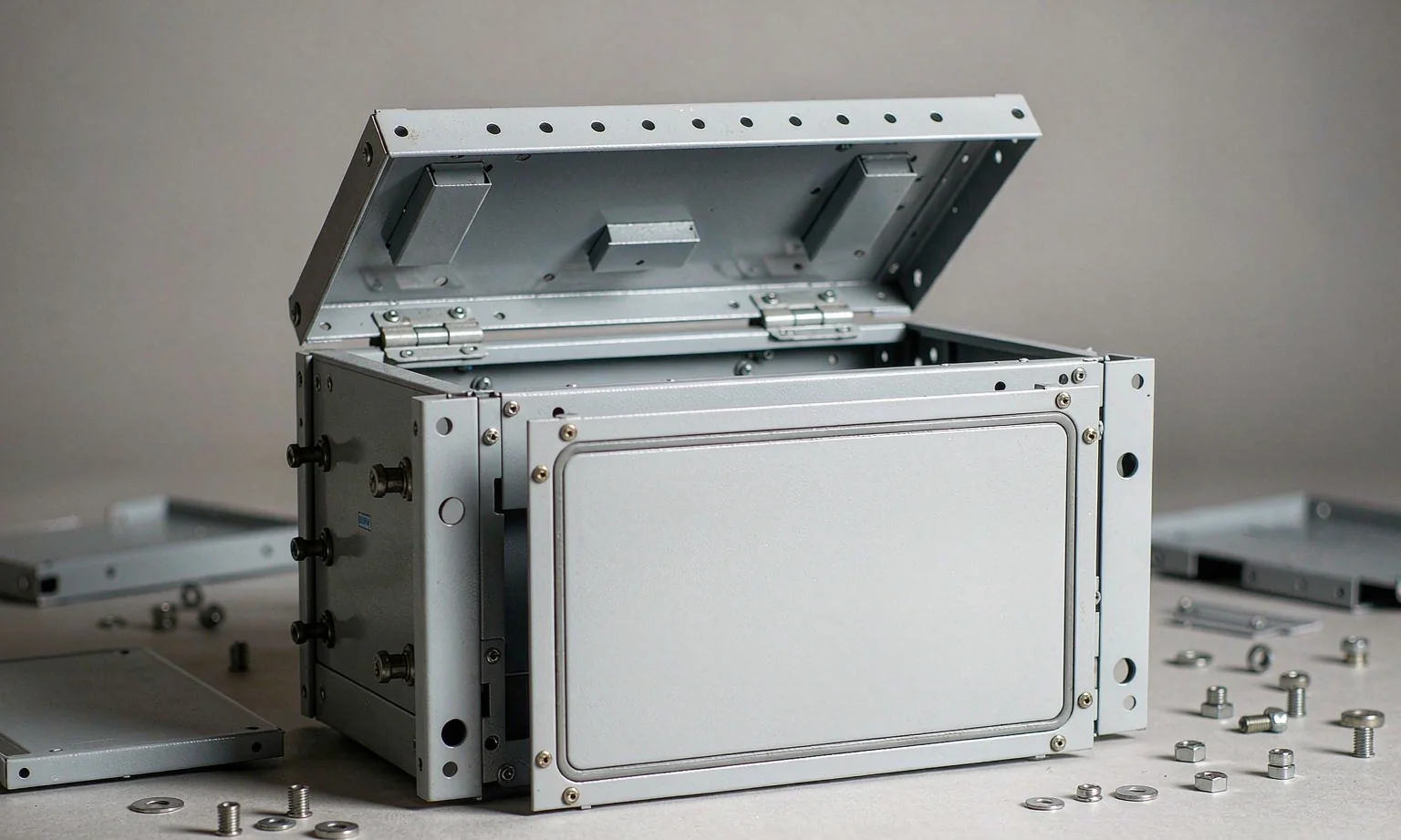
How to Design Sheet Metal Enclosures for Assembly (DFM Guide)
Updated: 2026-09-14 · ZEROALU Engineering
Quick answer: A sheet metal enclosure is easy to assemble when four things are designed in from the start: bend relief at every bend intersection, self-locating tab-and-slot features, a fastener strategy matched to whether the joint must be serviceable, and a tolerance budget that assumes parts will stack. Get those four right and assembly becomes a one-person, no-adjustment operation; get them wrong and every unit needs a file, a clamp, and a fitter.
Most enclosure problems we see are not manufacturing defects — they are assembly problems designed in at the drawing stage. A bracket that needs two people to hold, a lid that will not close once the gasket is fitted, a rivnut that spins because the sheet is too thin: all of these trace back to decisions made before the first blank was cut. This guide covers the assembly-driven design rules we apply when reviewing customer drawings, with the failure each rule prevents and the tolerance numbers that make them work.
What does DFM for sheet metal enclosures actually mean?
DFM (design for manufacturing) for a sheet metal enclosure means designing the part so that it can be cut, bent, welded, finished, and assembled using standard tooling and a predictable sequence — without special fixtures, hand fitting, or rework. In practice, the assembly half of DFM is the half that costs the most money at volume, because every extra minute of assembly is repeated on every unit you ship. A 30-second saving on a 5,000-piece program is 42 hours of labour.
The discipline is not about making parts "prettier." It is about removing decisions from the shop floor: parts that can only go together one way, joints that need no measurement, and tolerances that are loose enough to be routine but tight enough to seal. If you are new to the broader set of sheet metal cost drivers, start with our 10 DFM tips that cut sheet metal cost and lead time, then come back here for the assembly-specific detail.
Rule 1: Bend relief at every bend intersection
When a bend runs into another bend or into a formed flange, the material has nowhere to go. Without relief, the corner tears, the flange distorts, and the two faces that were supposed to meet at 90° no longer line up — which you then discover at assembly. Add a relief notch with a width at least equal to the material thickness and a depth slightly greater than the bend radius, with a radius at the notch root. Sharp internal corners in a relief notch act as stress risers and can crack during forming or in service vibration.
The same logic governs bend radius. For mild steel such as SPCC, an inside radius of roughly one material thickness is a safe default; stainless steel and 5052 aluminum need a larger radius for the same thickness because of their lower elongation. Our bending design guide covers bend allowance, K-factor, and relief geometry in detail — the assembly consequence is simple: a torn corner or a distorted flange is an assembly defect, even though it originates in the press brake.
Rule 2: Make parts self-locating with tabs and slots
The single highest-leverage assembly feature in sheet metal is the tab-and-slot joint. A tab laser-cut into one part that enters a matching slot in another does three things at once: it locates the parts in X and Y, it holds them at the correct angle while the welder works, and it removes the need for a fixture or a second pair of hands. Design tabs 0.1–0.2 mm narrower than the slot so they drop in without force but leave no visible gap after welding.
Two design details make tabs reliable. First, give the tab a small lead-in chamfer or radius so it can find the slot when the operator is working quickly. Second, add a self-fixturing feature such as a half-shear or a small twist tab that holds the joint closed without clamping. Where tabs are not practical, use interlocking edge features or a shallow dimple-and-hole pair. The goal in every case is the same: the part should hold itself in position before any permanent joining happens. This is also the cheapest quality control you can build in, because a part that physically cannot be assembled wrong cannot be assembled wrong. For more on how these choices interact with production volume, see our prototype-to-mass-production guide.
Rule 3: Choose the fastener strategy before the geometry
The joining method determines hole sizes, edge distances, access requirements, and whether the enclosure can ever be opened again. Deciding it late — after the panel layout is fixed — is the most common cause of expensive redesign. The table below compares the methods we run in production.
| Method | Serviceable? | Access needed | Best for | Watch out for |
|---|---|---|---|---|
| Spot welding | No | Both sides | Permanent steel joints at volume | Electrode marks on visible faces; poor on aluminum |
| Blind rivets | No (destructive) | One side | Closed boxes, mixed materials, low volume | Mandrel heads left in the enclosure; vibration loosening |
| Rivnut / self-clinching nut | Yes | One side (install) | Threaded joints on thin sheet; lids and access panels | Spins if sheet is below the minimum thickness; hole size must match the insert |
| Self-clinching standoff | Yes | One side (install) | Mounting PCBs and internal brackets to a base panel | Height tolerance stacks with board thickness |
| Clinch / TOX joint | No | Both sides (tool) | Dissimilar metals, coated sheet, no heat allowed | Requires dedicated tooling; not for high-load joints |
| Screws + tapped flange | Yes | One side | Low volume, thick sheet (≥2 mm), field service | Limited thread engagement on thin sheet; cross-threading |
Two rules of thumb from production. First, if the enclosure will ever be opened — for maintenance, firmware, or inspection — do not spot-weld or rivet the access panel; use captive screws into rivnuts so the fasteners stay with the enclosure and cannot be lost or dropped inside. Second, respect the minimum sheet thickness for self-clinching hardware; a rivnut installed in material thinner than the insert's rating will spin under torque, and that failure appears only after the enclosure is in the customer's hands. If your design mixes steel and aluminum, also read our SPCC vs SUS304 vs 5052 material comparison on galvanic corrosion at fastened joints.
Rule 4: Budget tolerances for the stack, not the part
A single bracket at ±0.2 mm is easy. Four brackets welded to a frame, each at ±0.2 mm, can put the final mounting face 0.8 mm out of position — and now the lid does not close. Assembly tolerances accumulate, so the question is never "is this part accurate enough?" but "is the final assembly accurate enough after every part contributes its error?"
Apply the general tolerance standard to non-critical features and reserve tight tolerances for the few dimensions that actually mate. Under ISO 2768-m (medium), a 100 mm feature carries roughly ±0.3 mm; ISO 2768-f (fine) tightens that considerably. Specifying the whole drawing to a fine class multiplies cost with no assembly benefit. Instead: use clearance holes 0.2–0.5 mm larger than the fastener nominal, and make one part in each mating pair slotted so the assembly can absorb the stack without adjustment. Our sheet metal tolerance guide explains how to choose between the two classes feature by feature.
Rule 5: Design the weld for access and distortion control
A joint that cannot be reached cannot be welded — at least not well. Check that the torch or electrode can physically reach every weld with the correct angle, and that the heat will not damage an adjacent finished surface. Where access is tight, changing the joint type (tab-and-slot with a single stitch weld instead of a full seam) is usually cheaper than building a special fixture. Our TIG vs MIG vs laser welding comparison covers heat input and distortion for each process.
Distortion is the second half of the problem. Long continuous welds pull the panel out of flat; balanced stitch welds, back-stepping, and symmetrical weld sequences keep the heat even. On a large enclosure, design the weld sequence into the drawing notes rather than leaving it to the operator, and specify clamping or tacking in the fixture. Distortion found after finishing is the most expensive defect to correct, because the finish has to be stripped before the part can be straightened.
Rule 6: Give gaskets a continuous, uniform sealing surface
If the enclosure must meet an IP rating, the seal is a compression system, not a gasket lying on a flange. Provide a continuous flange at least 8–10 mm wide, with generous corner radii and no interruptions, and space the fasteners so the gasket is compressed evenly along its whole length. A flange that narrows at a corner, or a fastener pattern that leaves a 150 mm unsupported span, will leak — not because the gasket failed, but because the design allowed it to lift.
Design the lid and base as a matched pair: the same flange width, the same corner radii, and fastener positions that align once both parts have accumulated their tolerances. Where a sealed enclosure also needs EMI shielding, the gasket often has to do both jobs, which constrains the flange design further. Our IP rating guide covers the test conditions each rating implies.
Rule 7: Plan the assembly sequence and the finish around it
Sketch the assembly order before finalising the drawing. Which part goes in first? Can the last part be fitted with the first part already in place? Is there a step where an internal component must be installed before a panel is closed? Designs that ignore sequence usually fail at the last step — the classic case being a PCB that cannot be inserted because a welded lip blocks its path. Asymmetric features, keyed connectors, and one-way tabs remove the remaining ambiguity: the part should only fit the correct way.
Finish interacts directly with assembly. Powder coating adds roughly 0.06–0.1 mm per coated surface, which is enough to close a nominal clearance or jam a sliding fit; specify coating thickness and account for it in mating dimensions. Mask threaded inserts, grounding contact points, and EMI mating surfaces before coating, because a coated thread will not accept a screw cleanly and a coated ground point will not conduct. Decide early whether the finish is applied before or after assembly — pre-finish protects the weld areas but risks damage during assembly, while post-finish avoids assembly damage but requires masking every interface. Our powder coating vs anodizing comparison covers the thickness and masking trade-offs.
Assembly DFM checklist for your next drawing
Run this list before releasing a drawing for quotation:
- Bend relief present at every bend-to-bend and bend-to-flange intersection, with a radiused root.
- Tab-and-slot or interlocking features so parts self-locate before welding.
- Fastener strategy chosen and annotated — serviceable joints use captive hardware, permanent joints use weld or rivet.
- Minimum sheet thickness checked against the self-clinching fastener data sheet.
- Hole clearance 0.2–0.5 mm on assembly holes; one part slotted wherever a stack can accumulate.
- Tolerance class stated (ISO 2768-m by default, fine only on mating features).
- Weld access and sequence noted, with balanced or stitch welds on large panels.
- Sealing flange continuous, 8–10 mm minimum, with even fastener spacing for IP-rated designs.
- Assembly sequence sketched, and the last part confirmed to be fittable.
- Coating thickness and masking specified for threads, grounds, and mating faces.
Material and thickness choices affect all of the above, so pair this checklist with our gauge thickness chart and the fiber laser vs CNC punching guide when you are settling the blank-level decisions.
Frequently asked questions
What is the minimum bend radius for a sheet metal enclosure?
As a working default, an inside radius equal to one material thickness is safe for mild steel. Stainless steel and 5052 aluminum typically need 1.5–2× thickness or more because of lower elongation, and the safe minimum rises as thickness increases. Where a tight radius is essential, cutting a relief or choosing a more formable alloy is usually cheaper than forcing the bend.
Should I use rivnuts or welded nuts on a thin enclosure panel?
Rivnuts and self-clinching nuts are normally the better choice, because they install from one side and give a clean thread without heat distortion. Welded nuts suit thicker material and high-vibration joints but add a welding operation and can distort a thin panel. Whichever you choose, confirm the panel thickness against the insert manufacturer's minimum — an undersized panel is the most common cause of a spinning insert.
How much clearance should I leave between mating sheet metal parts?
For fastener clearance holes, 0.2–0.5 mm over nominal is a practical range that assembles without force while keeping the joint visually tight. For locating features such as tab-and-slot, 0.1–0.2 mm is enough to drop in by hand. Anything tighter risks a part that will not go together on a bad day; anything looser produces visible gaps and a joint that shifts under load.
Does powder coating affect how the enclosure assembles?
Yes. Powder coat typically adds 0.06–0.1 mm per coated surface, which is enough to close a nominal clearance, stiffen a sliding fit, or stop a screw entering a coated thread. Specify the coating thickness, mask threads and grounding points, and remember that a coating build-up on two mating faces accumulates on both sides.
How do I stop tolerance stack-up from breaking a welded enclosure?
Limit the number of dimensions that must be tight. Use general tolerances for non-critical features, reserve fine tolerances for the mating faces only, and make one part in each pair slotted so the assembly can absorb accumulated error. Where possible, locate parts from a common datum rather than chaining dimensions through several components.
When should I use tabs and slots instead of a fixture?
Whenever the assembly would otherwise need a second pair of hands or a locating fixture, tabs and slots are almost always cheaper — they are cut in the same laser pass as the rest of the profile, so they add essentially no cost, while a welded fixture adds cost to every unit and takes floor space. They are less suitable where the tab would interfere with a sealing surface or where a fully flush exterior face is required.
Want your enclosure drawing reviewed for assembly?
Send us your STEP or DXF file. We will return a DFM review covering bend relief, self-locating features, fastener selection, tolerance stack-up and sealing, with a quote for the revised design.
Request a Free Quote →