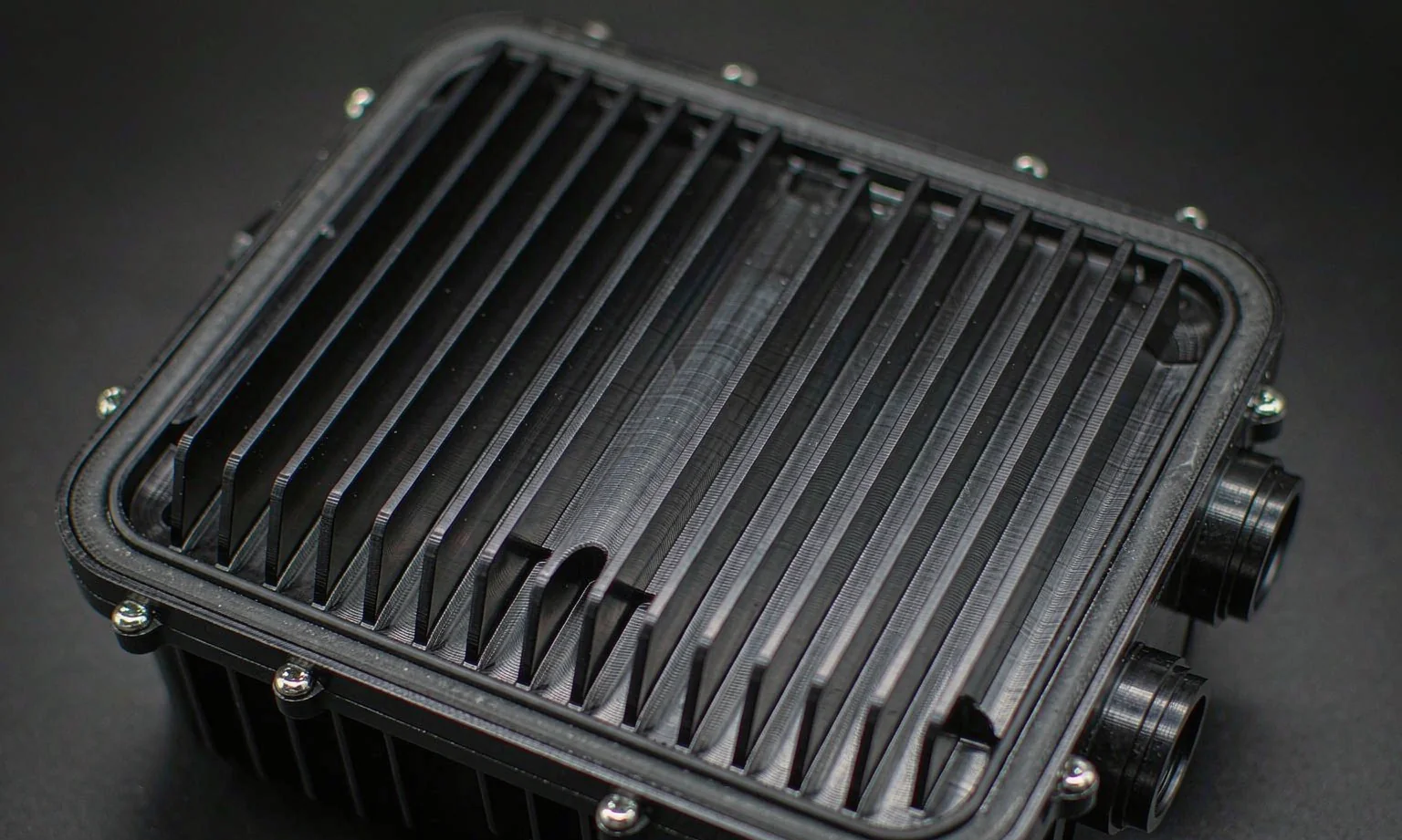
How Do You Keep a Sealed Aluminum Electronics Enclosure Cool?
Updated: 2026-09-15 · ZEROALU Engineering
Quick answer: A sealed aluminum enclosure cools itself by conducting heat from the source to the wall and then rejecting it to ambient air. For a typical 300 × 200 × 120 mm black-anodized box, that works out to roughly 30–35 W at a 25 °C rise above ambient. Above that, the practical sequence is: improve conduction and surface finish first, add fins or a larger radiating area second, and only then consider forced air, an air-to-air heat exchanger, or liquid cooling.
Thermal management is the single most common reason a sealed enclosure project comes back for redesign. The electronics are specified, the IP rating is fixed, the mounting footprint is fixed — and then someone calculates that the internal air will sit 30 °C above ambient and every electrolytic capacitor in the unit loses half its life. This guide covers the cooling options we run in production for aluminum enclosures, the numbers that decide between them, and the design changes that buy thermal headroom without breaking the seal.
What actually sets the temperature inside a sealed enclosure?
The internal temperature is the ambient temperature plus the sum of every thermal resistance between the heat source and the outside air, multiplied by the dissipated power. The chain has four links: junction-to-case inside the component, case-to-enclosure-wall through the mounting interface, conduction through the wall, and convection plus radiation from the outer surface to ambient. Designers usually obsess over the first link (the datasheet θJC) and ignore the fourth, which for a sealed enclosure is almost always the largest.
Two consequences follow. First, the outer surface is the bottleneck, so any change that increases its area or its heat transfer coefficient buys more than an expensive change to the internal path. Second, the thermal resistance of the aluminum wall itself is almost never the limiting factor. The difference between 6061 (about 167 W/m·K) and 6063 (about 200 W/m·K) is around 20%, but conduction through a 3 mm wall is a tiny fraction of the total resistance. Spending money on a higher-conductivity alloy while leaving the surface unpainted is a poor trade. If you are still choosing material, our 6061 vs 6063 vs 7075 comparison covers the trade-offs.
Option 1: Passive cooling — conduct heat to the wall
Passive cooling has no moving parts, no filtration, no maintenance and no impact on ingress protection. It should be the default, and it is sufficient more often than people assume provided the surface does its job. The outer wall rejects heat by two mechanisms at once: convection to the surrounding air, and radiation to any cooler surface it can see.
Finishing is the cheapest thermal upgrade available. Bare mill-finish aluminum has an emissivity of only about 0.05–0.10, so it radiates almost nothing no matter how hot it gets. Anodizing or painting raises emissivity to roughly 0.80–0.85. Measured as an effective heat transfer coefficient for a cabinet wall, that is the difference between roughly 3.7 W/(m²·K) unpainted and 5.5 W/(m²·K) coated — about 50% more heat rejection for a finish you were probably specifying anyway for corrosion resistance. Our Type II vs Type III anodizing comparison covers which finish to choose.
Engineers sometimes worry that the anodic layer or a powder coat insulates the part. It does not, at these thicknesses. A 20 µm anodic layer at a conductivity of about 2 W/m·K adds a thermal resistance of roughly 1 × 10⁻⁵ m²·K/W. A 100 µm powder coat adds about 2.5 × 10⁻⁴ m²·K/W. Both are negligible next to the 0.18 m²·K/W of the air film on the outside. The finish helps far more than it hurts.
Option 2: Forced air — when a fan earns its place
A fan changes the problem entirely, because moving air removes heat by mass flow rather than by surface area. The relationship is:
P (W) ≈ 0.335 × Q (m³/h) × ΔT (K)
At a 10 K air temperature rise, that is about 3.35 W for every 1 m³/h of airflow — so a 100 m³/h fan moves roughly 335 W of heat.
That number is far larger than passive cooling, which is exactly why the fan is so tempting — and why it is so often over-specified. The figure describes heat carried away by the exhaust air, not heat removed from a hot component. Internal components still have to transfer their heat into that moving air, which depends on airflow actually reaching them rather than short-circuiting from inlet to outlet. Ducting, baffles and component placement decide whether the fan performs to its curve or to a fraction of it.
The real cost of a fan in a sealed product is the ingress protection. Any opening for airflow is a path for dust and water, so a fan is normally incompatible with IP66 and above. Filter fans can hold IP54 or IP55 with regular filter changes; below that, you are maintaining a consumable, and a clogged filter turns a 300 W cooling system into a 100 W one without any warning. If the enclosure must stay genuinely sealed, skip to the next option.
Option 3: Closed-loop and liquid cooling — moving heat without moving air
When the enclosure has to stay sealed but passive cooling is not enough, the answer is to move heat across the wall without piercing it. Three approaches cover most industrial applications:
Air-to-air heat exchangers use an internal and an external fan over a shared metal core. The enclosure stays sealed at IP66 or better while transferring heat through the core. Capacity is typically 15–60 W/K of temperature difference, so they suit medium loads in dusty or washdown environments.
Heat pipes and vapour chambers move heat isothermally from a small hot source to a large cool wall. Effective thermal conductivity is commonly 10,000–100,000 W/m·K against roughly 400 for solid copper, which is exactly what you want when a single component concentrates 100 W into a footprint the size of a postage stamp. This is the standard solution for high-power electronics in sealed aluminum housings — see our heat sink design guide and the aluminum heat sink bodies we machine for that role.
Liquid cold plates are the highest-capacity option and the only one that scales to kilowatts. A machined aluminum cold plate with an internal channel or a milled serpentine can hold a surface within a few degrees of the coolant temperature at extremely high flux. The trade-off is that the enclosure now depends on an external coolant loop, so it only makes sense where that infrastructure exists — EV and industrial power electronics, not a wall-mounted junction box. Thermoelectric (Peltier) coolers exist as well, but with a coefficient of performance of roughly 0.3–0.6 they are only worth considering when the electronics must run below ambient.
Comparison: cooling options for aluminum electronics enclosures
| Method | Practical capacity | Seal integrity | Maintenance | Best for |
|---|---|---|---|---|
| Passive, bare aluminum | ~3.7 W/(m²·K) | Full (IP66+) | None | Low-power, indoors, cost-driven |
| Passive, anodized or coated | ~5.5 W/(m²·K) | Full (IP66+) | None | Default choice — best value per watt |
| Finned / extruded body | 2–4× plain wall | Full (IP66+) | Dust between fins | 10–100 W in a sealed box |
| Filter fan | 250–600 W typical | IP54/IP55 only | Filter replacement | Cabinet installations with maintenance access |
| Air-to-air heat exchanger | 15–60 W/K | Full (IP66+) | Two fans | Sealed + dusty or washdown |
| Heat pipes / vapour chamber | 50–500 W hot-spot | Full (IP66+) | None | Concentrated heat in a sealed housing |
| Liquid cold plate | 1 kW+ | Full, with fittings | Coolant loop | EV, traction and industrial power electronics |
Read the table in order. Each step down adds cost, complexity or a maintenance obligation, so the discipline is to confirm that the row above genuinely cannot meet the budget before moving. A large share of "we need a fan" conclusions disappear when the enclosure is anodized, mounted with an air gap instead of flush against a panel, and given a machined floor thick enough to spread heat away from the hot spot. For housings in this class, see our inverter aluminum enclosures and OBC / power-electronics housings.
Six design rules that buy thermal headroom
- Finish the radiating surfaces. Anodize or powder coat the outside faces. Emissivity from 0.05 to 0.8 is worth roughly 50% more heat rejection, and it costs nothing extra if the finish was already specified for durability.
- Mount with an air gap. An enclosure bolted flat to a wall loses most of one face to conduction into a surface that may be hotter than ambient. Standoffs of 10–15 mm restore both convective and radiative area on that face.
- Use a machined floor, not sheet, under the hot spot. A 5–6 mm machined base spreads heat laterally far better than 1.5–2 mm sheet. Spreading resistance, not through-thickness conduction, is what keeps a small die hot.
- Never mount a power device dry to the wall. Bare metal-to-metal contact between two machined surfaces is a poor thermal joint because only a small fraction of the nominal area actually touches. A thermal pad or gap filler at 1–3 °C/W costs cents and is often the difference between passing and failing.
- Space natural-convection fins widely. For passive cooling, 10–12 mm fin gaps let air in and out; tighter fins add surface area the air cannot reach. In forced air the logic inverts — 2–4 mm gaps are then correct, which is another reason not to design fins before deciding the cooling method.
- Vent the pressure, not the enclosure. A sealed box breathes through its gasket as it heats and cools, drawing in moisture that condenses on cold surfaces. A proprietary IP68 breather membrane equalises pressure without admitting water, and it is far cheaper than the field failures it prevents.
How to estimate whether your enclosure needs a fan
Work the numbers before adding hardware. Take a sealed enclosure of 300 × 200 × 120 mm, anodized aluminum, in still air at 35 °C ambient, and suppose the electronics can tolerate 60 °C internally.
- External area: 2 × (0.30×0.20 + 0.30×0.12 + 0.20×0.12) = 0.24 m².
- Available rise: 60 − 35 = 25 K.
- Heat transfer coefficient: about 5.5 W/(m²·K) for an anodized surface in natural convection.
- Dissipation: 5.5 × 0.24 × 25 ≈ 33 W.
So this enclosure handles roughly 30–35 W passively, and the number scales linearly with both area and permitted rise. Anything beyond that has to come from more surface (fins, a larger box, a heat pipe to a remote wall) or moving air. Two caveats matter in practice. First, if the enclosure is mounted flat or sits in a rack with restricted airflow, derate the area by 30–50%. Second, the internal air will be warmer than the wall, so the component itself sees a worse number than the calculation implies — add the internal air-to-wall resistance when the source is small and concentrated.
One more reason to take the estimate seriously: electrolytic capacitor life roughly halves for every 10 °C increase in operating temperature. A design that runs at 85 °C instead of 65 °C can halve the service life of the product without failing any specification test at the prototype stage. Thermal margin is reliability, not just a datasheet line.
Thermal design checklist
- Total dissipation summed, with a realistic duty cycle rather than worst-case-only.
- Maximum internal and junction temperatures stated, and the allowed rise above the highest ambient the product will see.
- External area calculated, then derated for mounting conditions.
- Surface finish specified on all radiating faces, with emissivity in mind.
- Interface materials chosen for every component-to-wall joint — no dry metal-to-metal contact.
- Wall thickness under hot spots increased for spreading, or a heat pipe specified.
- Cooling method selected only after the passive options are quantified, and consistent with the required IP rating.
- Pressure equalisation defined for sealed designs.
- Verification plan agreed — thermocouples on the hottest component and on internal air, tested at maximum ambient and full load.
Thermal design sits alongside sealing and EMI as the three constraints that fight each other in a sealed enclosure: every opening that helps cooling hurts the ingress rating, and every metal-to-metal joint that helps EMI is another contact resistance in the thermal path. Our EMI shielding guide and IP65 vs IP67 comparison cover the other two, and the enclosure design guide covers the housing itself.
Frequently asked questions
How much heat can a sealed aluminum enclosure dissipate without a fan?
Roughly 5.5 W per m² of external surface per degree of permitted temperature rise, for an anodized or coated surface in free air. A 300 × 200 × 120 mm box has about 0.24 m² of surface, so at a 25 °C rise it dissipates about 33 W. Derate by 30–50% if the enclosure is mounted flat against a panel or in a restricted rack.
Does anodizing or powder coating reduce heat dissipation?
No — it substantially improves it. A 20 µm anodic layer adds a negligible thermal resistance, while raising surface emissivity from about 0.05 on bare aluminum to roughly 0.8. Measured as an effective coefficient, that takes a wall from about 3.7 W/(m²·K) to about 5.5 W/(m²·K), roughly 50% more heat rejection.
Can I use a fan on an IP66 enclosure?
Not directly. Any opening for airflow admits dust and water, so filter fans are normally limited to IP54 or IP55 and require filter maintenance. If the enclosure must hold IP66 or above, use an air-to-air heat exchanger, a heat pipe to an external wall, or a liquid cold plate instead — all three move heat across the wall without piercing it.
How do I size natural-convection cooling fins?
Keep fin gaps at roughly 10–12 mm and make the fins vertical so air can rise through the channels. Tighter spacing adds surface area that the air cannot reach, so it increases weight and cost without adding dissipation. Fin orientation and the free path of air in and out of the channels matter more than the total fin area.
Why does my hot component stay hot even though the enclosure is cool?
Because the bottleneck is the internal path, not the wall. The usual causes are a small contact area, a dry metal-to-metal joint, insufficient wall thickness to spread heat before it reaches the surface, or still internal air that cannot carry heat to the wall. A thermal interface pad and a thicker machined floor under the device often solve it without changing the external design at all.
Do I need a breather vent on a sealed enclosure?
If internal air cycles between hot and cold, yes. The enclosure breathes through its gasket as the internal pressure changes, drawing in moisture-laden air that condenses on cold surfaces and eventually causes corrosion or shorts. An IP68-rated breather membrane equalises pressure while keeping water out, and it is inexpensive compared with the failures it prevents.
Need a sealed aluminum housing that meets a thermal budget?
Send us your STEP file with the internal dissipation and your maximum ambient. We will review wall thickness, spreading, finish and any requirement for fins, heat pipes or a cold plate — and return a DFM review with a quotation.
Request a Free Quote →